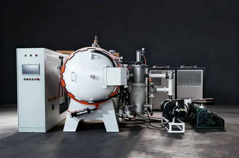
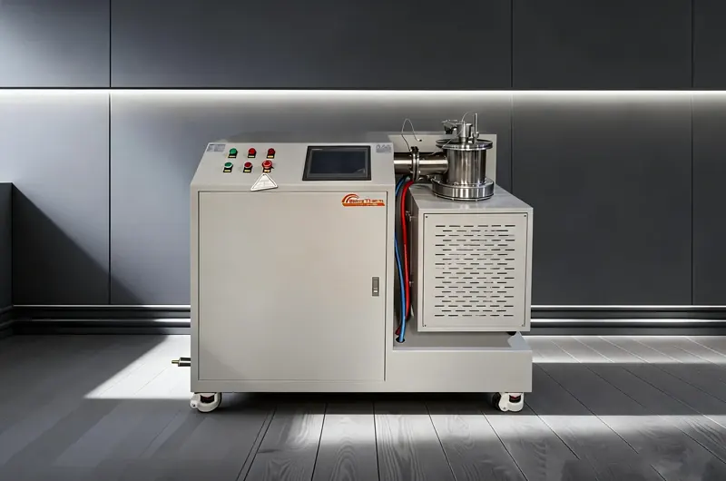
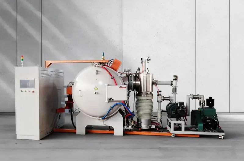
- 100% Flux-Free Process
- ±3°C Temperature Uniformity
- Vacuum to 5×10⁻⁴ Pa
- Zero Post-Braze Cleaning
- CE · ISO 9001 Certified
What Is Vacuum Brazing
Joining Metals Without Flux,
Without Oxidation, Without Compromise
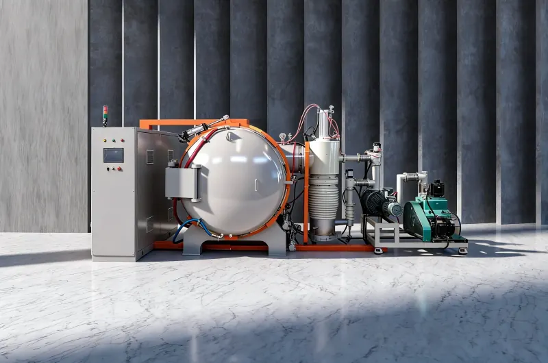
Vacuum brazing is a metal joining process in which a filler metal (brazing alloy) is melted and flowed between two or more base metal components inside a sealed vacuum chamber. The absence of atmospheric oxygen eliminates oxidation of both the base metal and the filler — removing the need for flux entirely and producing joints with exceptional cleanliness, strength, and appearance.
Unlike conventional brazing methods that require flux to prevent oxidation and subsequent acid cleaning to remove flux residues, vacuum brazing produces a ready-to-use, oxide-free, flux-residue-free joint in a single furnace cycle. This makes it the preferred joining method for aerospace heat exchangers, medical implant components, precision electronic assemblies, and cutting tool production.
Brother Furnace vacuum brazing furnaces maintain working vacuum throughout the entire heating, brazing, and cooling cycle — ensuring the joint surface remains uncontaminated from room temperature to peak brazing temperature and back to discharge temperature.
-
No Flux — No Cleaning Required
Vacuum atmosphere replaces flux entirely. No flux residue means no acid cleaning, no contamination risk, and no hidden corrosion under joints.
-
Joint Strength Equal to Parent Material
Oxide-free filler flow and perfect wetting produce brazed joints with tensile strength matching or exceeding the base metal in many alloy combinations.
-
Multiple Joints in One Cycle
Entire assemblies with dozens or hundreds of joints can be brazed simultaneously in a single furnace cycle — dramatically reducing cost per joint versus manual methods.
-
Precise Thermal Control Prevents Distortion
Uniform heating within ±3°C across the entire load eliminates thermal gradients that cause warping and dimensional change in precision assemblies.
-
Dissimilar Metal Joining
Vacuum brazing reliably joins dissimilar metals — stainless steel to copper, titanium to ceramic, carbide to steel — combinations impossible with conventional welding.
Vacuum Brazing Process — Step by Step
-
Part Preparation & Filler Placement
Clean surfaces, apply filler foil, paste, or preform
-
Chamber Evacuation
Pump down to working vacuum 10⁻³–10⁻⁴ Pa
-
Controlled Heat-Up
Programmed ramp rate, hold at intermediate temp to equalise load
-
Brazing Hold
Hold at peak temp, filler melts and flows into joint gap
-
Controlled Cooling
Programmed cool-down, gas quench option available
-
Discharge & Inspection
Vent, unload — no cleaning required, joints ready for inspection
Product Series
Three Series, One Platform — Built for Every Application
From high-volume tool brazing to ultra-clean aerospace-grade joining, Brother Furnace offers a purpose-engineered vacuum brazing furnace series for every requirement level.
The heat-resistant steel Vacuum series is Brother Furnace's entry-level vacuum brazing platform, designed for general industrial applications where cost-effectiveness and reliable performance are the primary requirements.
The furnace chamber is fabricated from high-grade heat-resistant steel alloy, providing a clean vacuum environment suitable for brazing stainless steel assemblies, carbon steel components, copper alloy heat exchangers, and general metalwork.
Working temperature up to 1150°C — covers the full range of silver, copper,
and
nickel-based brazing alloys
Vacuum to 1×10⁻³ Pa — sufficient for oxide-free brazing of steel and copper
alloy
assemblies
Temperature uniformity ±5°C across the working zone — suitable for
medium-precision assemblies
Lower capital cost versus molybdenum muffle series — best for cost-sensitive
production environments
Programmable multi-segment temperature profiles via PLC — supports complex
brazing
cycles
Available in horizontal and vertical configurations to suit workshop
layout
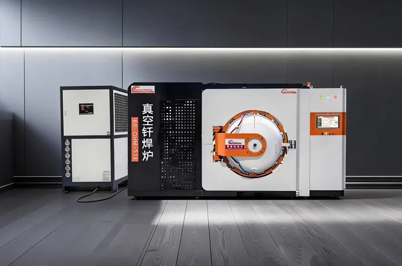
The molybdenum strip Vacuum series represents the highest performance tier in the Brother Furnace vacuum brazing range. The muffle is constructed from pure molybdenum strip elements — a refractory metal with a melting point of 2623°C — enabling operating temperatures up to 1350°C and working vacuum levels to 5×10⁻⁴ Pa.
This series is the standard choice for aerospace heat exchangers, medical device components, titanium alloy assemblies, and precision electronic packages where the absolute highest joint cleanliness is mandatory.
Working temperature up to 1350°C — enables brazing of nickel superalloy and
refractory metal assemblies
Vacuum to 5×10⁻⁴ Pa — ultra-low partial pressure of oxygen and nitrogen for
the
most reactive alloys
Temperature uniformity ±3°C across the working zone — required for aerospace
and
medical specifications
Molybdenum muffle generates zero carbon contamination — essential for titanium
and
reactive alloy brazing
Full batch data logging — vacuum level, temperature profile, and cycle time
recorded per load for AS9100 compliance
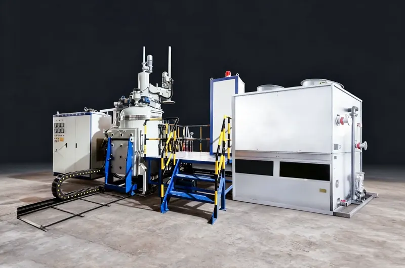
The vacuum tool brazing furnace is purpose-designed for the cutting tool manufacturing industry. It addresses the specific requirements of brazing cemented carbide (WC-Co) inserts to steel shanks, polycrystalline diamond (PCD) and CBN tool blanks to steel bodies, and diamond saw segments to steel cores — all processes that require precise temperature control, flux-free atmosphere, and high production throughput.
The furnace features a large working zone with optimised fixture design to maximise load density per cycle.
Working temperature up to 1100°C — optimised for silver-copper and copper-zinc
brazing alloys used in tooling
Vacuum to 1×10⁻³ Pa — eliminates oxidation of carbide and steel surfaces
without
flux
Large working zone with modular fixture system — maximise tools per cycle for
high-volume production
Uniform heating eliminates thermal stress cracking of carbide inserts — a
common
failure mode in flame brazing
Controlled cooling rate prevents residual stress and carbide delamination
after
brazing
Key Advantages
Why Vacuum Brazing Outperforms
Every Alternative
Eight technical and operational advantages that make vacuum brazing — and Brother Furnace equipment — the preferred choice for engineers specifying joining processes for critical applications.
Completely Flux-Free
The vacuum atmosphere replaces flux entirely. No flux means no flux residue, no corrosive chemicals in the joint, no post-braze acid cleaning, and no risk of hidden corrosion under flux inclusions in service.
±3°C Temperature Uniformity
Uniform heating across the entire working zone within ±3°C ensures all joints in a loaded furnace reach the correct brazing temperature simultaneously — eliminating under-brazed cold spots and over-heated zones that cause distortion.
Parent-Metal Joint Strength
Oxide-free filler wetting and capillary flow into a correctly designed joint gap produces a brazed interface with tensile and shear strength matching or exceeding the parent metal — verified by destructive testing to aerospace standards.
Batch Processing — Many Joints per Cycle
Entire assemblies with hundreds of joints, or thousands of small components, can be processed in a single furnace cycle. This makes vacuum brazing orders of magnitude more cost-effective than manual torch or induction brazing for production volumes.
Dissimilar Metal Capability
Vacuum brazing reliably joins material combinations impossible by welding: stainless steel to copper, titanium to ceramic, cemented carbide to steel, Kovar to alumina. The flux-free vacuum environment enables wetting of oxide-forming surfaces that would be unwettable in air.
Minimal Distortion
Controlled, uniform heating and cooling eliminates the thermal gradients responsible for warping and dimensional change. Precision assemblies exit the furnace within drawing tolerance — no straightening or re-machining required.
Superior Surface Finish — No Post-Processing
Vacuum-brazed joints and component surfaces emerge from the furnace bright, oxide-free, and ready for final inspection or assembly. There is no scale, no discolouration, no flux staining, and no need for abrasive cleaning, pickling, or passivation. This is particularly valuable for medical implant components and visible aerospace hardware where surface condition is part of the specification.
Full Process Traceability for Quality Systems
Every furnace cycle is logged automatically: vacuum level at each stage, temperature profile across all control zones, cycle start/end times, operator ID, and any alarms. Data is stored per batch and exportable in CSV or PDF format — providing the complete documentation trail required for AS9100 aerospace, ISO 13485 medical device, and ISO 9001 quality management systems.
Brazing Process
The 6-Stage Vacuum Brazing Cycle
Every Brother Furnace vacuum brazing cycle follows a defined six-stage protocol. Understanding each stage enables optimisation of cycle time, joint quality, and furnace throughput.
01
Part Preparation & Filler Placement
All components are cleaned of oils, oxides, and contaminants by degreasing and, where necessary, light abrasive cleaning. Brazing filler metal is applied in the correct form — foil, paste, wire preform, or clad sheet — and positioned at or near the joint gap. Components are fixtured to maintain correct joint clearance (typically 0.05–0.15 mm) throughout the heating cycle.
Joint gap control is the single most important factor in vacuum brazing quality. Gaps
too
wide
result in weak, porous joints; gaps too narrow prevent filler flow. 0.05–0.15 mm is the
target
for most filler/base metal combinations.
02
Loading & Chamber Evacuation
The loaded fixture is placed in the furnace working zone and the chamber is sealed. The vacuum pump system activates sequentially — roughing pump, then Roots blower, then diffusion or turbomolecular pump — reducing chamber pressure to the working vacuum level (1×10⁻³ to 5×10⁻⁴ Pa) before heating begins. This pump-down phase typically takes 15–30 minutes.
Never begin heating until the target vacuum level is achieved and stable. Starting the
heat
cycle with insufficient vacuum results in surface oxidation of the base metal and
filler,
causing poor wetting and joint voids.
03
Controlled Heat-Up with Intermediate Hold
Temperature is increased at a controlled ramp rate — typically 5–15°C/min depending on component mass and material — to avoid thermal shock and ensure temperature equalisation across the load. An intermediate hold (typically at 500–600°C for 15–30 minutes) allows the entire load to reach thermal equilibrium before continuing to the brazing temperature, preventing localised overheating of thin sections.
For assemblies with large mass variation between components, a second intermediate
hold near
the
filler solidus temperature (50–80°C below brazing temp) is recommended to ensure uniform
heat
soak before filler melting begins.
04
Brazing Hold at Peak Temperature
The furnace is held at the brazing temperature (above the filler liquidus) for a defined time — typically 5–20 minutes — sufficient for the filler to melt completely, wet the base metal surfaces, and flow by capillary action to fill the joint gap. The vacuum environment ensures the filler wets the oxide-free base metal surface without any flux assistance. Optical pyrometers and thermocouples monitor temperature in real time.
Avoid excessive hold time at peak temperature. Over-holding causes filler erosion of
the
base
metal (particularly in thin-wall stainless steel) and can cause filler to flow out of
the
joint
gap by gravity if the fixture design allows.
05
Controlled Cooling
After the brazing hold, the furnace cools at a controlled rate. The initial cooling phase (from brazing temperature to filler solidus) must be slow enough to allow the filler to solidify uniformly without cracking. Below 500°C, the cooling rate can be increased. For applications requiring rapid cooling — post-braze solution annealing or age hardening — an optional gas quench (nitrogen or argon backfill) is available on selected models.
For carbide-to-steel tooling joints, a slow controlled cool through the 700–400°C
range is
critical to minimise residual thermal stress at the carbide-steel interface — the
primary
cause
of carbide cracking in tool brazing.
06
Venting, Unloading & Inspection
Once the load temperature drops below 150°C (monitored by thermocouple), the chamber is vented to atmosphere and the fixture is unloaded. Components emerge with bright, oxide-free surfaces and clean joints — no cleaning, pickling, or passivation required. Visual inspection and dimensional check can begin immediately. All cycle data is automatically saved to the batch record for quality documentation.
Bright, silvery joint fillets with smooth meniscus profiles indicate good vacuum and
correct
filler flow. Dull, granular, or porous fillets indicate insufficient vacuum or incorrect
peak
temperature — review the batch data log to identify the root cause.
Applications
Industries That Rely on Vacuum Brazing
From single-crystal turbine blades to diamond cutting tools — if the joint must not fail, vacuum brazing is the process.
Aerospace & Defence
Turbine engine heat exchangers, fuel system manifolds, bleed air ducting, and avionics cooling assemblies.
Vacuum brazing is specified by Boeing, Airbus, and GE Aviation for titanium and nickel alloy assemblies where zero flux contamination is mandatory.
Ti alloys · Inconel · Stainless · Kovar
Cutting Tools & Tooling
Cemented carbide inserts to steel shanks, PCD and CBN tool blanks, diamond saw blade segments, and drill bit assemblies.
Vacuum brazing eliminates the thermal cracking and flux contamination problems inherent in flame brazing of carbide tools.
WC-Co Carbide · PCD · CBN · HSS Steel
Medical Devices & Implants
Surgical instrument assemblies, endoscope components, orthopaedic instrument handles, and implantable device housings.
ISO 13485 compliance requires the flux-free, residue-free process that only vacuum brazing provides.
Ti-6Al-4V · 316L SS · CoCrMo · Nitinol
Electronics/Microwave
Hermetic microwave packages, waveguide assemblies, power amplifier housings, and vacuum electronic devices.
Vacuum brazing joins Kovar, copper, and ceramic components with hermetic, flux-free seals that meet MIL-STD-883 leak test requirements.
Kovar · OFHC Copper · Alumina · Molybdenum
Automotive & EV
Turbocharger impeller assemblies, EGR coolers, transmission oil coolers, and battery thermal management plates.
Vacuum brazing is specified by Boeing, Airbus, and GE deliver leak-free performance at high pressure and temperature cycling.
Aluminium · Stainless Steel · Copper · Brass
Power Generation & Energy
Gas turbine combustor liner assemblies, heat recovery steam generator components, nuclear fuel assembly hardware, and solar collector absorber panels.
Vacuum brazing is specified by Boeing, Airbus, and GE provides the high-temperature joint integrity required for continuous service above 800°C.
Hastelloy · Inconel · Stainless · Titanium
Chemical & Process Industry
Plate heat exchangers, pressure vessel internals, corrosion-resistant piping assemblies, and analytical instrument components.
Vacuum brazing is specified by Boeing, Airbus, and GE provides the high-temperature joint integrity required for continuous service above 800°C.
316L SS · Hastelloy C · Nickel · Titanium
Research & Specialised Manufacturing
Particle accelerator components, scientific instrument vacuum systems, semiconductor process equipment, and cryogenic assemblies.
Vacuum brazing is specified by Boeing, Airbus, and GE ultra-clean, leak-tight joints required for ultra-high vacuum (UHV) and cryogenic service.
OFHC Copper · SS 304L · Alumina · Kovar
Technical Comparison
Vacuum Brazing vs. Atmosphere Brazing vs. Flame Brazing
A direct comparison of the three most common industrial brazing methods across the parameters that matter most to engineers and quality managers.
| Parameter | Vacuum Brazing | Atmosphere Brazing | Flame / Torch Brazing |
|---|---|---|---|
| Flux Required | None — flux-free | None (protective gas) | Yes — mandatory |
| Post-Braze Cleaning | None required | Light cleaning | Acid flux removal required |
| Joint Surface Condition | Bright, oxide-free | Clean but may discolour | Oxidised, flux-stained |
| Temperature Uniformity | ±3°C across load | ±5–10°C | Operator-dependent, ±30°C+ |
| Batch Processing | Full batch — 100s of joints per cycle | Batch possible | One joint at a time |
| Dissimilar Metal Joining | Excellent — titanium, ceramic, carbide | Limited | Very limited |
| Distortion Control | Minimal — uniform heating | Moderate | High — localised heating |
| Process Repeatability | Excellent — fully programmable | Good | Poor — operator skill dependent |
| Quality Documentation | Full batch data log — AS9100 ready | Partial logging | Manual records only |
| Reactive Metal Capability | Titanium, zirconium, niobium | Limited | Not suitable |
| Typical Applications | Aerospace, medical, electronics, tooling | Automotive, HVAC | Plumbing, simple assemblies |
Why Brother Furnace
The Vacuum Brazing Furnace Partner You Can Rely On
15+ years of vacuum furnace engineering. 500+ installations across 40+ countries. Every furnace is engineered, manufactured, tested, and supported entirely in-house.
01 /
Application Engineering
We review your base metal, filler alloy, joint design, production volume, and quality requirements before recommending a series. Every quotation is engineered for your specific process — not a generic catalogue selection.
02 /
In-House Manufacturing
Vacuum chambers, heating elements, power supplies, and control panels are all designed and manufactured in our own facilities. No subcontracted assembly — full quality control from raw material to final acceptance test.
03 /
Factory Acceptance Testing
Every furnace undergoes full FAT before shipment: vacuum leak test, temperature uniformity survey (±3°C verification), control system check, and witnessed brazing trial on customer-representative parts where required.
04 /
Turnkey Installation and Training
Our field engineers travel to your site for installation, commissioning, and operator training. We do not consider a project complete until your team has successfully run qualification brazing cycles to your internal specification.
05 /
Lifetime After-Sales Support
Spare parts, heating element supply, process troubleshooting, and remote diagnostics are available for the full operating life of your furnace. Critical production issues receive a response within 24 hours from our technical support team.
-
2008Founded
-
500+VIM Installations
-
40+Countries Served
-
24 HSupport Response
FAQ
Frequently Asked Questions
Answers to the most common questions our customers ask before selecting and ordering a vacuum sintering furnace.
What is the difference between the heat-resistant steel muffle and molybdenum strip muffle series?
The heat-resistant steel muffle series operates up to 1150°C with vacuum to 1×10⁻³ Pa and temperature uniformity of ±5°C — suitable for general industrial brazing of stainless steel, carbon steel, and copper alloy assemblies. The molybdenum strip muffle series operates up to 1350°C with vacuum to 5×10⁻⁴ Pa and temperature uniformity of ±3°C — required for aerospace, medical, and titanium alloy applications where the highest joint cleanliness and tightest temperature control are mandatory. The molybdenum muffle also generates zero carbon contamination, which is critical when brazing reactive metals.
What brazing filler metals are compatible with vacuum brazing furnaces?
Vacuum brazing is compatible with a wide range of filler metals: silver-based alloys (BAg series, 600–900°C), copper and copper-zinc alloys (BCu, BCuZn, 900–1100°C), nickel-based alloys (BNi series, 900–1200°C), gold-based alloys for electronics (BAu series, 900–1100°C), and palladium-containing alloys for high-temperature aerospace applications. Note that zinc-containing fillers (such as BCuZn) have high vapour pressure and are not recommended for vacuum brazing — zinc evaporates under vacuum and contaminates the furnace. Silver-copper eutectic (BAg-8, 72Ag-28Cu) is the most commonly used filler for vacuum brazing of stainless steel and copper assemblies.
Can vacuum brazing furnaces also be used for heat treatment?
Yes. Vacuum brazing furnaces can perform vacuum annealing, solution annealing, stress relieving, and age hardening in the same equipment. Many customers run brazing and heat treatment in the same furnace cycle — for example, brazing a titanium assembly and simultaneously solution annealing it. Models with gas quench capability (nitrogen or argon backfill) can also perform quench hardening after brazing. This dual-use capability significantly improves furnace utilisation and return on investment.
What is the correct joint gap for vacuum brazing?
The optimal joint gap for vacuum brazing is typically 0.05–0.15 mm (50–150 microns) at brazing temperature. This range provides the capillary force needed to draw molten filler into the joint while maintaining sufficient space for complete filler penetration. Gaps below 0.05 mm restrict filler flow and cause incomplete fill; gaps above 0.15 mm reduce capillary force and result in weak, porous joints. Note that the gap must be specified at brazing temperature — thermal expansion of the assembly at temperature must be accounted for in the fixture and joint design. Contact our engineering team for joint design guidance specific to your material combination.
How do I select between the three Brother Furnace brazing series?
Selection depends on your base material, required temperature, vacuum level, and quality standard: (1) If you are brazing stainless steel, carbon steel, or copper alloys for general industrial applications and cost is a primary consideration — the Heat-Resistant Steel Muffle series is the right choice. (2) If you are brazing titanium alloys, nickel superalloys, or any assembly requiring aerospace or medical certification — the Molybdenum Strip Muffle series is required. (3) If your primary application is brazing cemented carbide, PCD, or CBN cutting tools at high production volume — the Vacuum Tool Brazing Furnace series is purpose-designed for your needs. Contact our team with your specific application and we will recommend the optimal series and working zone size.
Can aluminium be brazed in a vacuum furnace?
Yes, but aluminium vacuum brazing requires special consideration. Aluminium has a tenacious natural oxide layer (Al₂O₃) that must be disrupted for the filler to wet the surface. In vacuum brazing, this is achieved through the use of magnesium as a getter — either incorporated into the filler alloy (Al-Si-Mg fillers) or placed as a separate Mg source in the furnace. The Mg evaporates under vacuum and reacts with the Al₂O₃, disrupting it and enabling filler wetting. Aluminium vacuum brazing requires very precise temperature control (the brazing window is typically only 5–10°C wide) and vacuum levels of 1×10⁻⁵ Pa or better. Contact our engineering team to discuss whether our equipment is suitable for your specific aluminium brazing application.
What utilities are required to install a vacuum brazing furnace?
Three main utility requirements: (1) Electrical supply — 3-phase power at the rated furnace kW plus approximately 20% for ancillaries; standard voltage options are 380V/50Hz, 415V/50Hz, and 480V/60Hz. (2) Cooling water — a closed-loop chilled water system at the specified flow rate, with inlet temperature below 30°C; cooling water is required for the vacuum chamber walls, power feedthroughs, and vacuum pump. (3) Inert gas supply — nitrogen or argon at 99.999% purity for backfill during cooling and chamber purging; a standard gas cylinder manifold is sufficient for most laboratory and small production furnaces. Detailed utility specifications are provided in the project engineering package after order confirmation.
How long does a typical vacuum brazing cycle take?
A typical vacuum brazing cycle for a medium-sized load (50–200 kg gross weight) takes 4–8 hours from chamber door close to discharge: pump-down 15–30 minutes, heat-up with intermediate hold 90–180 minutes, brazing hold 10–20 minutes, controlled cooling 120–240 minutes, and venting/unloading 10–15 minutes. Cycle time is dominated by the cooling phase — the load must cool slowly to avoid thermal stress. Gas quench capability can reduce cooling time by 40–60% for applications where rapid cooling is acceptable. Smaller loads in laboratory furnaces can complete a cycle in 2–4 hours.
What is included in the standard delivery of a Brother Furnace vacuum brazing furnace?
Standard delivery includes: vacuum furnace chamber and frame, heating element assembly (heat-resistant steel or molybdenum muffle as specified), vacuum pump system, PLC control system with HMI touchscreen, temperature controller and thermocouple assembly, vacuum gauge system, cooling water manifold and connections, electrical interconnection cables, operation and maintenance manual, CE certificate, and factory acceptance test report including temperature uniformity survey data. Site installation and commissioning services are available and strongly recommended — contact us for a complete turnkey project quotation.
What is the lead time and warranty for Brother Furnace vacuum brazing furnaces?
Standard lead time is 45–75 days for standard configurations from order confirmation to factory acceptance testing, depending on furnace size and working zone specification. Custom configurations and larger furnaces may require 90–120 days. The standard warranty is 12 months from commissioning date or 18 months from shipment date, whichever comes first, covering manufacturing defects in the furnace chamber, heating elements, vacuum system, and control system. Consumable items including heating elements (after normal service life), vacuum pump oil, and door seals are excluded from the warranty coverage.
Also From Brother Furnace
Related Vacuum Furnace Products
Explore our full range of industrial vacuum furnaces — all engineered and manufactured in-house at Brother Furnace.