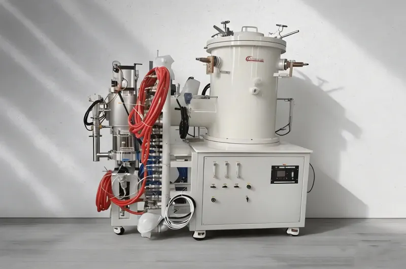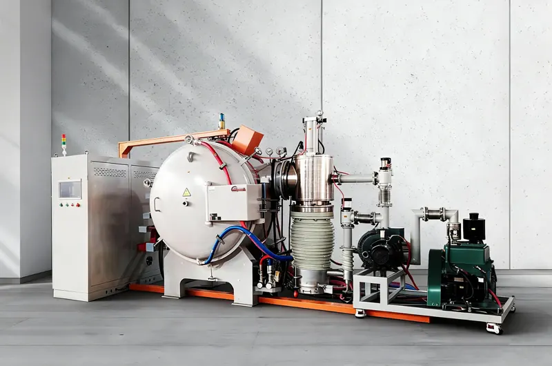
A vacuum debinding and sintering furnace removes the polymer binder from a moulded or pressed part between 100 and 700 °C, then takes the same load to sintering temperature without a cool-down, a door opening or a second pump-down. Both stages run in one chamber, on one recipe and one pump set. The design suits parts that cannot survive being moved: MIM green bodies, pressed carbide carrying a wax lubricant, and ceramic parts with a green bending strength of 5 to 15 MPa.
Why the two stages share one chamber
A green part is mostly binder
An MIM green body carries 35 to 45 percent binder by volume. A wax or soluble fraction fills the pore channels and a backbone polymer holds the particles together, and both have to leave in order. Gas generated faster than it can diffuse out raises internal pressure; on 316L feedstock, micro-cracking appears at 0.2 to 0.5 MPa of local pressure against a green bending strength of only 5 to 15 MPa.
What a second furnace costs
Two furnaces mean a cool-down in air, a manual transfer and a second evacuation between the two stages. Green bodies are fragile and hygroscopic, so every transfer adds breakage, surface oxidation and handling hours that never appear in a quotation.
The trade-off is contamination. Binder vapour condenses on any surface below 150 °C, and part of it is still in the chamber when the sintering ramp begins. A vacuum debinding and sintering furnace is specified around that from the first cycle: a heated exhaust line, a vapour trap sized to the binder mass per batch, and a hot zone that can be cleaned without a rebuild.
The process window
Most MIM and cemented carbide routes follow the process window below, and a vacuum debinding and sintering furnace runs all of it as one recipe. Holds belong where the feedstock's thermogravimetric curve shows a mass-loss step, and the figures are working ranges rather than a recipe. A 5 kg load runs 12 to 20 hours, with about half of it in debinding.
| Stage | Temperature | Atmosphere / pressure | Ramp | Function |
|---|---|---|---|---|
| Purge | 20 – 100 °C | N₂ or Ar flow, 0.1 MPa | — | Removes air and moisture before heat is applied |
| Early debinding | 100 – 250 °C | Partial pressure, 1 – 5 kPa | 1 – 3 °C/min | Melts and evaporates the wax fraction |
| Main debinding | 250 – 500 °C | Partial pressure with sweep flow | 0.5 – 2 °C/min | Decomposes the backbone polymer |
| Residual removal | 500 – 700 °C | Vacuum, 10 Pa or better | 2 – 5 °C/min | Strips the last volatiles before the body closes |
| Sintering ramp | 700 °C to setpoint | Vacuum, 0.1 – 10 Pa | 5 – 10 °C/min | Necks form, then the body densifies |
| Sintering hold | 1250 – 1550 °C | Vacuum or partial-pressure argon | — | Densification to final density |
| Controlled cooling | Setpoint to 600 °C | Vacuum, then argon backfill | Furnace rate | Limits thermal shock and shortens the tail |
Purge and early debinding
Water leaves first. Absorbed moisture and light volatiles come off below 120 °C, and a hold at that temperature keeps the steam from blistering a part whose pores are still sealed. The wax fraction melts between 100 and 250 °C, where a partial pressure of 1 to 5 kPa carries vapour toward the exhaust instead of letting it sit static over the load.
Main debinding, the slow stage
The backbone polymer decomposes between 250 and 500 °C, and the ramp through that band decides whether the part comes out clean. A rate of 0.5 to 2 °C/min is normal; 3 to 5 °C/min generates volatiles three to four times faster and blisters a 5 mm section. Mass loss sets the endpoint rather than the clock, because residue still being released when the pore channels close has nowhere left to go.
Residual removal before the body closes
Between 500 and 700 °C the last decomposition species leave under a vacuum of 10 Pa or better. The stage has a measurable endpoint: exhaust dew point stops falling, and each sweep recovers pressure at the same rate as the one before it. A load that enters the sintering ramp while it is still releasing gas traps that gas as porosity, and no hold time closes porosity formed that way.
Sintering and cooling
Densification runs at 1250 to 1550 °C in vacuum or partial-pressure argon, depending on alloy. Backfilling argon at 600 °C shortens the tail of the cycle by hours, and below 200 °C the load can meet air without scaling.
How a recipe is proved before production
Three measurements prove a recipe. Mass loss to 700 °C has to land within half a percentage point of the binder content measured on the feedstock, exhaust dew point has to stop falling before the sintering ramp starts, and a sectioned part has to show no porosity at the core at 50× magnification. A recipe that passes on one test bar still needs a full tray, because a heavy load lengthens the vapour path and pushes the debinding peaks 20 to 40 °C above what a few grams show.
A recipe sheet carries those three values, the date and the load pattern. Every requalification after a binder lot change repeats all of them.
Where the debinding stage goes wrong
Most failures in the debinding stage of a vacuum debinding and sintering furnace are process failures rather than furnace faults, and each one leaves a different signature on the part.
| Symptom | Root cause | What to change |
|---|---|---|
| Blistered surface, internal porosity | Gas generated faster than it could diffuse out | Drop to 0.5 °C/min through 250 – 400 °C; raise partial pressure |
| Dark film on the load | Vapour broke down on the parts instead of leaving | Increase sweep flow; check exhaust path and trap; clean furniture |
| Slender parts sagging | No support once the binder is gone | Alumina setters or a powder bed; reduce stack height |
| Low sintered density | Residue blocking neck growth, or hold too short | Extend the 500 – 700 °C stage; verify hold time at the load |
| Colour or composition drift between batches | Inconsistent thermal history, not a material change | Lock the recipe; log exhaust dew point; verify the control thermocouple |
| Pump oil dark within weeks | Vapour condensing in the line ahead of the pump | Afterburner or cold trap; heat the pump line; shorten the oil interval |
Blisters that start inside the part
A blister is gas pressure that beat the diffusion rate, so section thickness sets the risk more than total binder mass does. A 5 mm wall generates vapour faster per square centimetre of surface than a 2 mm wall and has further to carry it, which is why thin parts tolerate 2 °C/min and thick ones do not. A slower ramp and a higher partial pressure change both terms at once.
A dark film on the load
Vapour that leaves the part faster than the sweep removes it breaks down on the load and on the furniture instead of leaving the chamber. The film is cosmetic on a test bar and a rejection on a visible surface. Sweep flow and a short exhaust path through the hot zone fix it; a static partial pressure does not.
Sagging once the binder is gone
A part with no binder has no strength to carry its own weight at 1000 °C. Alumina setters, a powder bed or a lower stack height carry it instead. Plan for 15 to 20 percent linear shrinkage on an MIM part and compensate in the mould, not in the furnace.
Density that comes in low
Low density after a clean-looking cycle usually traces to the 500 to 700 °C stage or to a hold that was timed but never measured at the part. A control thermocouple reading the hot zone can sit 20 to 40 °C above the load, which shortens every hold without changing the recipe.
The exhaust train decides pump life
Where vapour condenses
Wax leaves the hot zone at 250 to 450 °C and solidifies the moment it meets a surface below 150 °C. That surface is normally the pipework, a valve body or the pump inlet. Oil that darkens within a few weeks is the first symptom and a seized pump inside a year is the second.
Afterburner, cold trap, or both
An afterburner burns the vapour at 700 to 800 °C with added air and leaves a clean exhaust. A cold trap condenses it ahead of the pump, costs less, and needs emptying on a schedule set by the binder mass per cycle. A furnace running daily on a wax-based feedstock normally carries both.
One chamber or two
One chamber runs the whole cycle in a single hot zone: simpler, cheaper, and adequate to a few tens of kilograms per batch. Two chambers separate the stages with a transfer mechanism, so the sintering zone never sees vapour, the hot zone lasts longer and the two stages can overlap across batches. The cost is roughly double, plus a mechanism that has to work hot and reliably.
Two chambers pay back through hot zone life and scrap rate. For a plant running several tonnes a month that usually beats the doubled capital cost; below 20 to 30 kg per batch, a single chamber with a working afterburner is the sensible first purchase.
| Debinding and sintering furnace | Plain vacuum sintering furnace | Standalone debinding furnace | |
|---|---|---|---|
| Cycles per batch | One | One, after external debinding | One, plus a separate sinter cycle |
| Handling between stages | None | Fragile green body moved in air | Two transfers |
| Atmosphere across both stages | Continuous | Broken | Broken |
| Exhaust handling | Essential | Minimal | Essential |
| Best fit | MIM, pressed carbide and ceramic parts with binder | Parts that arrive clean | High-volume catalytic debinding ahead of other sintering assets |
Sizing the chamber to the load
Working volume against charge weight
MIM parts are small and arrive in quantity, so usable volume sets the purchase and charge weight only follows from how well the trays are filled. Standard hot zones for this duty run 300 × 300 × 600 mm to 600 × 600 × 900 mm. A 300 × 300 × 600 mm hot zone holds roughly 50 to 100 kg of green parts at 40 percent fill, and a 600 × 600 × 900 mm hot zone holds 250 to 500 kg.
Debinding scales with surface area rather than weight, and a chamber outside that envelope becomes a special build.
Tray packing and the 80 percent mistake
A tray packed to the edges comes out with a clean outer ring and a spoiled core, because vapour cannot leave the middle of the stack. Thirty to fifty percent volume utilisation is normal practice on a vacuum debinding and sintering furnace. The extra thirty points buy cycle time and pay for it in scrap.
| Parameter | Unit | Range |
|---|---|---|
| Maximum temperature | °C | 1600 design, 1550 working |
| Debinding temperature range | °C | 100 – 700 |
| Useful hot zone | mm | 300 × 300 × 600 to 600 × 600 × 900 |
| Charge weight | kg | 50 – 500 green parts |
| Ultimate vacuum, cold and empty | Pa | 1 |
| Working vacuum, sintering | Pa | 0.1 – 10 |
| Leak-up rate | Pa/h | 0.67 or better, corrected to chamber volume |
| Debinding partial pressure | kPa | 1 – 5, mass-flow controlled |
| Temperature uniformity | °C | ± 3 to ± 5, by zone count and chamber size |
| Exhaust handling | — | Afterburner, cold trap, or both |
| Control | — | Multi-segment recipe, mass-flow atmosphere, data logging |
What this furnace will not do
Four duties sit outside a vacuum debinding and sintering furnace, and each one has a different answer.
Catalytic debinding
Catalytic debinding needs an acid vapour atmosphere at 110 to 140 °C, usually nitric acid, inside a corrosion-resistant vessel. The thermal stage in this chamber takes over afterwards, for the backbone polymer that the acid leaves in place.
Pressure-assisted densification
Final density here comes from solid-state or liquid-phase sintering alone. Porosity that has to close under gas pressure needs 5 to 6 MPa of argon, which is the vacuum Sinter-HIP furnace; uniaxial loading at 20 to 50 MPa is the vacuum hot press furnace.
Titanium and other reactive alloys
Titanium picks up oxygen and nitrogen above 600 °C and forms a hard, brittle alpha case that no economic machining pass removes. The molybdenum strip chamber vacuum sintering furnace is built for that duty; this chamber is not.
Continuous production
High-volume MIM plants debind on pusher or mesh-belt lines, and a batch chamber sized to a shift is a different purchase from a continuous line. For laboratory batches where cycle time matters more than charge weight, spark plasma sintering reaches comparable density in minutes.
A wax-only duty that stops short of sintering runs cheaper on the vacuum dewaxing furnace, and gram-scale batches with little binder run on a ceramic fiber chamber.
Questions buyers ask
What separates debinding from dewaxing?
Dewaxing removes the wax fraction between roughly 100 and 300 °C. Debinding covers the whole binder system including the backbone polymer, to about 700 °C, and a vacuum debinding and sintering furnace carries the load straight into the sintering ramp.
Can both stages run without a cool-down?
Yes. The load stays under vacuum or partial pressure from door close to unload, so a green body never meets air at the point where it is weakest. The cycle also loses the ramp-down and ramp-up pair that a two-furnace route pays twice.
Can the chamber take cemented carbide with a wax lubricant?
Yes, and it is one of the most common duties here. Wax removal runs at 250 to 500 °C in vacuum or partial-pressure hydrogen, followed by sintering at 1380 to 1480 °C depending on grade.
How long does the hot zone last?
Heating elements and insulation are consumables, not lifetime parts. A chamber running daily on a wax feedstock typically needs elements at 6 to 12 months and a full insulation rebuild at 12 to 24 months, and a weak sweep flow shortens both by letting vapour break down inside the hot zone instead of leaving it.
How long is a full cycle?
Twelve to twenty hours for a 5 kg load, with about half of it in debinding. Section thickness moves that figure more than charge weight does: a 15 mm wall needs 30 to 48 hours of thermal debinding against 12 to 24 hours for a 4 mm wall.
Is hydrogen needed?
Some carbide and steel routes use partial-pressure hydrogen through debinding and early sintering to reduce oxides. Hydrogen is optional and alloy-dependent; where it is specified, the exhaust, the interlocks and the gas train are designed for it from the start.
What to send with an enquiry
Five inputs fix the chamber size, the pump set and the exhaust configuration, and the binder system is the one buyers leave out.
- Material and grade, including whether the alloy carries an interstitial limit.
- Green part weight and maximum section thickness.
- Binder system: wax, POM, or a route that is catalytically debound elsewhere.
- Target sintered density, or the property the finished part has to meet.
- Batch weight per shift and the hours available in that shift.
Those five settle more about the outcome than any other line on the specification. A route that needs pressure-assisted densification, a continuous line or a reactive alloy should say so in the first message, because this chamber covers none of the three and the vacuum sintering furnace range lists what does.