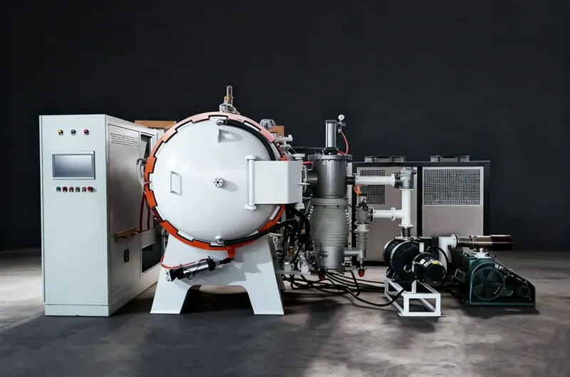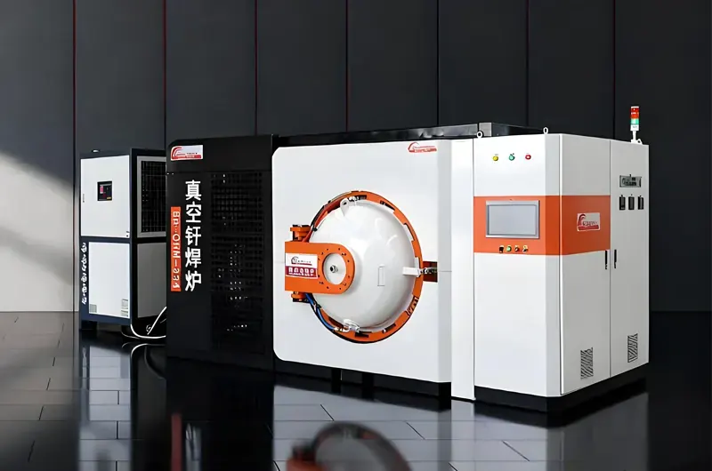
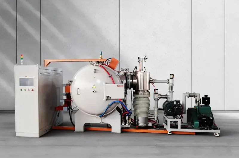
- 3-Stage Vacuum System
- IGBT 92%+ Efficiency
- EM Stirring — No Contact
- Vacuum-Locked Alloy Feeder
- Siemens / Mitsubishi PLC
What Is VIM?
Vacuum Induction
Melting Explained
Vacuum Induction Melting (VIM) is a primary melting process in which metallic charge materials are melted inside a sealed vacuum chamber using an electromagnetic induction coil.
The absence of atmospheric gases — oxygen, nitrogen, hydrogen — enables the production of alloys with purity levels impossible to achieve by any open-air melting route.
VIM is the mandatory first step for aerospace turbine alloys, medical implant materials, NdFeB permanent magnets, and nuclear-grade zirconium alloys.
-
Vacuum Environment Eliminates Gas Pickup
At 7×10⁻³ Pa, the partial pressures of O₂ and N₂ are effectively zero. Dissolved gas levels in the melt drop to fractions of what is achievable in air.
-
Electromagnetic Induction Heats Without Contact
The induction coil never touches the melt. Lorentz forces simultaneously heat and stir the charge, ensuring chemical homogeneity throughout the entire melt volume.
-
Carbon-Oxygen Reaction Removes Dissolved Oxygen
During the refining stage, dissolved C reacts with dissolved O to form CO gas (C + O → CO↑), which is pumped away continuously, driving oxygen below 20 ppm.
-
Vacuum-Locked Feeder Adds Reactive Elements Precisely
Al, Ti, B, Zr are added after refining through an isolation-valve feeder — no vacuum break, no oxidation losses, Ti/Al accuracy ±0.05–0.12%.
Purity Comparison
VIM vs. Conventional Melting — The Number
Typical production results from identical alloy heats processed in VIM and conventional air induction furnaces.
-
VIM — Brother FurnaceOxygen Content<20ppmNitrogen Content<10ppmTi / Al Accuracy±0.12%max deviationAerospace / Medical Grade
-
Air Induction FurnaceOxygen Content>100ppmNitrogen Content>50ppmTi / Al Accuracy±0.3%typical deviationNot Suitable for Critical Alloys
-
VIM AdvantageOxygen Reduction5×betterNitrogen Reduction5×betterComposition Control3–6×tighterUnique: Tramp Element Removal
-
Reactive Element YieldAl Yield — VIM95–98%vs. 60–75% in airTi Yield — VIM93–97%vs. 50–70% in airMax Temperature+300°Cvs. air induction limitAll figures: typical production data
System Architecture
6 Core Components of a VIM Furnace
Every Brother Furnace VIM system integrates six purpose-engineered subsystems. Each is designed, manufactured, and tested in-house — no third-party assembly.
01
Vacuum Chamber & Frame
304 Stainless Steel · Double-Wall Water-Cooled
The vacuum-tight chamber is fabricated from 304 stainless steel with a double-wall water-cooled design. All penetrations — power feedthroughs, thermocouple ports, observation windows, vacuum connections — use metal-sealed flanges to maintain leak rates below 0.5 Pa·L/s. The chamber is sized to accommodate the crucible, induction coil, mould assembly, and alloy feeder within a single sealed envelope.
Leak Rate <0.5 Pa·L/s
Metal-Sealed Flanges
Hydraulic Tilt Mechanism
02
3-Stage Vacuum Pump System
Roughing → Roots Blower → Diffusion / Turbo
The three-stage pump train achieves 7×10⁻³ Pa working vacuum in 20–45 minutes. Stage 1: rotary vane roughing pump reduces pressure to ~10 Pa. Stage 2: Roots blower accelerates to ~0.5 Pa. Stage 3: oil diffusion or turbomolecular pump reaches the process vacuum target. Cold traps prevent pump oil backstreaming into the chamber.
20–45 Min Pump-Down
Cold Trap Backstream
Protection
Continuous Leak Monitoring
03
IGBT Medium-Frequency Power Supply
500–3000 Hz · 35–400 kW · 92%+ Efficiency
IGBT solid-state technology converts grid power to medium-frequency AC at over 92% efficiency — 15–20% better than older SCR designs. Operating frequency is matched to charge mass: 2000–3000 Hz for small laboratory heats, 500–800 Hz for large industrial furnaces. Precise 10–100% power control enables accurate temperature ramp rates and stable refining holds throughout the melting cycle.
92%+ Electrical Efficiency
10–100% Power Control
500–3000 Hz Range
04
Crucible & Induction Coil
MgO / ZrO₂ / Al₂O₃ / CaO · Water-Cooled Coil
The crucible is the only component in direct contact with the melt. Material selection is critical: MgO for nickel superalloys and steels; ZrO₂ for titanium alloys; CaO for high-aluminium TiAl intermetallics; Al₂O₃ for stainless steels and non-reactive alloys. The water-cooled copper induction coil surrounds the crucible without contact — its electromagnetic field simultaneously heats the charge and induces vigorous Lorentz-force stirring for chemical homogeneity.
4 Crucible Material Options
EM Stirring — No Contact
Up to 2000°C Operating Temp
05
Vacuum-Locked Alloy Feeder
Multi-Hopper · Isolation Valves · No Vacuum Break
Reactive elements — aluminium, titanium, boron, zirconium — are added to the melt after refining through a vacuum-locked feeder without breaking chamber vacuum. An isolation valve and intermediate lock chamber allow the hopper to be loaded at atmospheric pressure while the main chamber remains at full process vacuum. This enables the sequential addition strategy that achieves ±0.05–0.12% compositional accuracy — impossible without this system.
No Vacuum Break Required
Multi-Hopper Configuration
±0.05–0.12% Accuracy
Enabled
06
PLC Control & Data Acquisition
Siemens S7 / Mitsubishi Q · Full Batch Logging
Siemens S7 or Mitsubishi Q-series PLCs manage all furnace functions: vacuum pump sequencing, power ramp profiles, pyrometer temperature monitoring, feeder valve actuation, and hydraulic tilt sequencing. All process variables are logged at configurable intervals and stored per batch — vacuum level at pour time, power profile, melt temperature history, addition timestamps. Data exports in CSV or PDF format for AS9100 and ISO 9001 documentation.
Siemens / Mitsubishi PLC
Full Batch Traceability
Remote Monitoring Access
Crucible Guide
Crucible Material Selection Guide
Crucible material selection is the most critical VIM process decision. The wrong choice causes melt contamination, crucible failure, or both. Use this guide to select the correct material for your alloy system.
MgO
Magnesia
Max 1800°C
✓ Best For
Nickel superalloys (IN718, IN625, Waspaloy), cobalt alloys, tool
steels, stainless steels. Industry standard for most VIM applications.
Avoid with high-Al alloys (>4% Al) — MgO reacts with Al
ZrO₂
Zirconia
Max 1900°C
✓ Best For
Titanium alloys (Ti-6Al-4V, Ti-6242), zirconium alloys, reactive
metal research. Lower reactivity with Ti than Al₂O₃.
Avoid with very high Al content (>6% Al)
Al₂O₃
Alumina
Max 1750°C
✓ Best For
Stainless steels, low-Al nickel alloys, copper alloys, precious
metals. Cost-effective for non-reactive alloys.
Never use with titanium alloys — Ti reduces Al₂O₃, causing O contamination
CaO
Calcia
Max 2000°C
✓ Best For
High-Al titanium alloys (TiAl intermetallics >45% Al),
ultra-clean
superalloys. Lowest reactivity with Al and Ti.
Highly hygroscopic — strict pre-bake & dry storage required
C
Graphite
Max 2500°C
✓ Best For
Copper alloys, aluminium alloys, precious metals (Au, Ag, Pt),
non-ferrous metals. Highest temperature capability.
Never use with steels or superalloys — causes carburisation
Important: CaO crucibles are highly hygroscopic and must be stored in a dry
environment and pre-baked at 300–400°C for a minimum of 4 hours before use. Failure to do so
results
in crucible cracking and potential melt leakage. Contact Brother Furnace engineering for
alloy-specific crucible recommendations before ordering.
Operating Process
The 7-Stage VIM Melting Cycle
Every Brother Furnace VIM heat follows a defined seven-stage protocol — from charge preparation to ingot discharge.
01
Charge Preparation &
Loading
All charge materials are cleaned, dried, and weighed to the
heat
recipe. Oxide scale, cutting fluids, and moisture must be eliminated before loading
—
these are the primary sources of oxygen and hydrogen contamination. Large pieces are
loaded first to protect the crucible from impact; smaller pieces and master alloys
fill
the remaining volume.
Pre-bake hygroscopic charge materials at 200–300°C for 2+ hours. Residual moisture is
the
leading cause of elevated hydrogen in the final ingot.
02
Chamber Evacuation
The chamber is sealed and the 3-stage pump train activates
sequentially. The roughing pump reduces pressure from atmosphere to ~10 Pa in 5–10
minutes. The Roots blower accelerates to ~0.5 Pa. The diffusion or turbomolecular
pump
then achieves the 7×10⁻³ Pa process target. Total pump-down time is typically 20–45
minutes depending on chamber volume and leak rate.
If pump-down time increases by more than 20% versus baseline, perform a leak check
before
proceeding. Elevated leak rates directly increase oxygen and nitrogen in the final melt.
03
Melting Stage
Power is ramped progressively — typically 20–30% of rated
power
initially — to allow the charge to settle and avoid crucible thermal shock. Once
fluid,
power is increased to 80–100% to achieve full melt quickly. Electromagnetic stirring
circulates the melt continuously, ensuring temperature uniformity and accelerating
dissolution of all charge materials.
Avoid rapid power increase during initial melt-in. Thermal shock to a cold crucible is
the
primary cause of premature crucible failure and potential melt leakage.
04
Refining Period
Once fully molten, the melt is held at temperature under
vacuum
for 15–30 minutes. Dissolved oxygen reacts with dissolved carbon (C + O → CO↑) — the
carbon-oxygen reaction — producing CO gas that is pumped away continuously. This is
the
primary oxygen removal mechanism in VIM. Volatile tramp elements (Pb, Bi, Sb, Se,
Te)
simultaneously evaporate under vacuum and are removed by the pump system.
Refining is complete when chamber pressure stabilises. A continuing pressure drop
indicates
ongoing CO evolution — extend the hold until pressure plateaus before adding reactive
elements.
05
Alloying &
Composition Adjustment
After refining is confirmed complete, reactive elements (Al,
Ti,
B, Zr, Nb) are added through the vacuum-locked alloy feeder without breaking chamber
vacuum. Each addition is timed and weighed precisely. The melt is stirred
electromagnetically for 3–5 minutes after each addition to ensure complete
dissolution.
A final temperature measurement confirms the melt is within the pour temperature
window.
Add reactive elements only after refining is confirmed complete. Adding Al or Ti before
the
C-O reaction finishes will consume these elements with residual oxygen, causing
under-composition.
06
Pouring
The furnace is tilted hydraulically (or bottom-poured for
larger
systems) to transfer the melt into the mould assembly — all under full vacuum. Pour
temperature and rate are controlled via the power supply. For VIM + VAR double-melt
routes, the VIM heat pours into cylindrical electrode moulds that become the VAR
consumable electrode.
For critical aerospace alloys, the VIM ingot is typically re-melted by VAR or ESR. VIM
provides chemical purity; VAR/ESR provides solidification structure refinement.
07
Solidification, Cooling
& Discharge
The ingot solidifies in the mould under vacuum or argon
backfill.
Cooling time depends on ingot mass — typically 30–90 minutes for ingots up to 100
kg.
Once the ingot surface temperature drops below 300°C, the chamber is vented and the
ingot discharged. Total cycle time: 2–4 hours for 100–300 kg heats; 4–8 hours for
1–2
ton industrial heats.
Argon backfill to ~0.05–0.1 bar during solidification reduces shrinkage porosity in the
ingot head and improves yield — standard practice for NdFeB and nickel superalloy heats.
Why VIM
8 Reasons VIM Is the Only Process for High-Purity Alloys
When your specification requires oxygen below 20 ppm, tight reactive element control, and zero electrode contamination — there is no alternative to vacuum induction melting.
01 /
Oxygen Below 20 ppm — Guaranteed
The vacuum environment eliminates atmospheric oxygen throughout
the
entire melt cycle. The C-O reaction during refining removes dissolved oxygen to below 20
ppm
— impossible in any open-air process. This directly eliminates oxide inclusions that
reduce
fatigue life in rotating components.
02 /
Nitrogen Below 10 ppm
Nitrogen solubility drops dramatically under vacuum. At
7×10⁻³
Pa,
nitrogen partial pressure is effectively zero, driving dissolved nitrogen out of the
melt
continuously. Final levels below 10 ppm are routinely achieved — versus 50–150 ppm
in
air-induction or AOD processes.
03 /
Reactive Element Control ±0.05–0.12%
Al and Ti are added after refining through the vacuum-locked
feeder
with no oxidation losses. Because oxygen is already below 20 ppm at the time of
addition,
virtually all added Al and Ti reports to melt composition — six times tighter
accuracy
than
air-induction practice.
04 /
Volatile Tramp Element Removal
Lead, bismuth, antimony, selenium, and tellurium — elements
that
embrittle grain boundaries — have high vapour pressures at steelmaking temperatures.
Under
VIM vacuum conditions these elements evaporate from the melt and are removed by the
pump
system. No other primary melting process achieves this.
05 /
Electromagnetic Stirring — No Mechanical Contact
Electromagnetic Stirring — No Mechanical Contact
The induction coil stirs the melt electromagnetically via the
Lorentz
force. No stirring paddles, lances, or gas injection that could introduce
contamination.
The
result is a chemically homogeneous melt with temperature uniformity typically within
±5°C
across the full melt volume.
06 /
92%+ Electrical Efficiency via IGBT
IGBT solid-state power supplies convert grid power to
medium-frequency AC at over 92% efficiency. Compared to older SCR-based systems
(75–80%
efficient), IGBT technology reduces energy consumption per tonne of melt by 15–20%,
lowering
operating costs and carbon footprint over the furnace lifetime.
07 /
Up to 2000°C Operating Temperature
With CaO or ZrO₂ crucibles, Brother Furnace VIM systems
operate
continuously at up to 2000°C — sufficient for refractory superalloys, TiAl
intermetallics,
and molybdenum-bearing alloys that cannot be processed in conventional induction
furnaces
limited to 1600–1700°C.
08 /
Full Batch Traceability for AS9100 & ISO 9001
Every process variable — vacuum level, power profile, melt
temperature, addition timestamps, pour time — is logged automatically and stored per
batch.
Exportable in CSV or PDF format, providing the complete documentation trail required
for
aerospace (AS9100), medical (ISO 13485), and nuclear quality systems.
Technical Comparison
VIM vs. Air Induction Melting — By the Numbers
Side-by-side data from identical alloy heats processed in VIM and conventional air induction furnaces. All figures are typical production results.
| Parameter | VIM — Brother Furnace | Air Induction Furnace | Improvement |
|---|---|---|---|
| Oxygen Content | <20 ppm | >100 ppm | 5× Better |
| Nitrogen Content | <10 ppm | >50 ppm | 5× Better |
| Ti / Al Accuracy | ±0.05–0.12% | ±0.3% | 3–6× Tighter |
| Tramp Element Removal | Pb, Bi, Sb, Se, Te removed | No removal | Unique to VIM |
| Oxide Inclusions | Minimal — no atmospheric oxidation | Significant — slag management required | Significantly Lower |
| Reactive Element Yield | Al: 95–98% · Ti: 93–97% | Al: 60–75% · Ti: 50–70% | 30–40% Higher |
| Max Operating Temp | 2000°C (CaO / ZrO₂) | ~1700°C (Al₂O₃) | +300°C |
| Electrical Efficiency | 92%+ (IGBT) | 75–80% (SCR) | 15–20% Lower Energy |
Industries Served
Where VIM-Processed Alloys Are Used
Vacuum induction melting is the entry point for the world's most demanding alloy applications. If the component cannot tolerate inclusions, gas porosity, or compositional variance — it starts in a VIM furnace.
Aerospace & Defence
Turbine discs, blades, and vanes in nickel superalloys. VIM is the
mandatory
first melt step for all rotating turbine hardware per AMS and NADCAP specifications.
IN718 · IN625 · Waspaloy · René 41 · Mar-M247
Medical Implants
Orthopaedic implants, spinal fusion devices, and dental prosthetics. ISO
5832
and ASTM F136 require oxygen below 0.13% — only achievable via VIM for reactive alloys.
Ti-6Al-4V · Ti-6Al-7Nb · CoCrMo · 316LVM
Permanent Magnets
NdFeB and SmCo master alloys for high-performance permanent magnets used
in EV
motors, wind turbines, and MRI machines. Oxygen control is critical for magnetic
performance.
NdFeB · SmCo · AlNiCo · FeNi
Nuclear Energy
Zirconium alloys for fuel rod cladding and nickel alloys for reactor
pressure
vessel components. Nuclear specifications require tramp element levels achievable only by
VIM.
Zircaloy-2 · Zircaloy-4 · Inconel 690 · Alloy 800H
Special Steels & Tool Steels
High-speed steels, bearing steels, and maraging steels where inclusion
cleanliness directly determines fatigue life and dimensional stability in service.
M2 · M42 · 52100 · M50 · 18Ni300 · H13
Electronic & Functional Materials
Soft magnetic alloys, precision resistance alloys, and shape memory alloys
where compositional precision of ±0.1% determines functional properties.
Nitinol · Permalloy · Mu-metal · Kanthal · Nichrome
Research & Development
Universities, national laboratories, and corporate R&D centres use
BR-KZG
laboratory VIM furnaces (5–50 kg) for new alloy development and small-batch prototype
production.
Custom Alloys · High-Entropy Alloys · ODS Alloys · Prototype Heats
Automotive & Energy
Turbocharger wheels, valve seat inserts, and high-temperature exhaust
components. EV drivetrain components increasingly specify VIM-processed NdFeB magnet alloys.
MAR-M · Stellite · NdFeB · Kovar · Invar
Installation Case
Study
January 2026
2-Ton VIM Furnace Installation —
Turkey
Aerospace Manufacturer
In January 2026, Brother Furnace completed the installation and commissioning of a 2,000 kg BR-RLL series vacuum induction melting furnace at a major aerospace component manufacturer in Turkey. The project was delivered turnkey: furnace design, manufacturing, factory acceptance testing (FAT) in China, sea freight, site installation, operator training, and process qualification.
The customer required a production VIM furnace capable of melting IN718 and IN625 nickel superalloy heats for turbine disc forgings, with oxygen content below 20 ppm and Ti/Al compositional accuracy within ±0.1%. The BR-RLL-2000 system — featuring a 400 kW IGBT power supply, 3-stage vacuum system achieving 7×10⁻³ Pa, MgO crucible, and Siemens S7 PLC — met all qualification criteria during the first production heat.
Commissioning was completed within 12 days of equipment arrival on site. The customer's quality team witnessed the qualification heats and confirmed all process parameters met their internal specification. The furnace entered full production operation in February 2026.
Project Results
-
2,000 kg
Furnace Capacity -
<20 ppm
Oxygen — Qualification Heat -
±0.08%
Ti/Al Accuracy Achieved -
12 Days
Site Commissioning Time
Why Brother Furnace
The VIM Partner You Can Rely On
15+ years of vacuum furnace engineering. 500+ installations across 40+ countries. Every VIM system is engineered, built, and supported by our in-house team.
01 /
Application Engineering
Our engineers review your alloy specification, production volume, and site conditions before recommending a system. No off-the-shelf proposals — every quote is engineered for your process.
02 /
In-House Manufacturing
Vacuum chambers, induction coils, power supplies, and control panels are all manufactured in our own facilities. Full quality control from raw material to final test — no third-party assembly.
03 /
Factory Acceptance Testing
Every furnace undergoes full FAT before shipment: vacuum leak test, power ramp test, control system verification, and witnessed melt trial. You receive a complete FAT report with your equipment.
04 /
Turnkey Installation Service
Our field engineers travel to your site for installation, commissioning, and operator training. We do not consider a project complete until your team has successfully run qualification heats.
05 /
Lifetime After-Sales Support
Spare parts, crucible supply, process troubleshooting, and remote diagnostics available for the full operating life of your furnace. Critical issues receive a response within 24 hours.
-
2008Founded
-
500+VIM Installations
-
40+Countries Served
-
24 HSupport Response
FAQ
Frequently Asked Questions
Answers to the most common questions our customers ask before selecting and ordering a vacuum sintering furnace.
Can the furnace capacity be customised?
Yes. Standard models range from 5 kg (BR-KZG-3) to 1,000 kg (BR-RLL-1000), but custom capacities from 5 kg to 2+ tons are available. Note that all capacity ratings are for steel (density 7.9 g/cm³). For titanium alloys (density ~4.5 g/cm³), the actual melt weight is approximately 57% of the rated figure. Provide your target alloy and melt weight when requesting a quote.
What utilities are required on site?
Three main utility requirements: (1) Electrical supply — 3-phase power at rated furnace kW plus ~20% for ancillaries; voltage options include 380V/50Hz, 415V/50Hz, and 480V/60Hz. (2) Cooling water — closed-loop chilled water at the flow rate specified per model (10–70 T/H), inlet temperature below 30°C. (3) Argon gas supply — 99.999% purity for backfill during solidification and chamber purging. Detailed utility specifications are provided in the project engineering package.
What is included in the standard delivery?
Standard delivery includes: vacuum furnace chamber and frame, IGBT medium-frequency power supply, 3-stage vacuum pump system, induction coil and crucible (first set), vacuum-locked alloy feeder, PLC control system with HMI touchscreen, optical pyrometer, hydraulic tilt system, cooling water manifold, electrical interconnection cables, operation and maintenance manual, CE certificate, and factory acceptance test report.
How long is the lead time and warranty?
Standard lead time is 60–90 days for models up to 100 kg, and 90–150 days for larger industrial systems, from order confirmation to factory acceptance testing. The standard warranty is 12 months from commissioning date or 18 months from shipment date, whichever comes first, covering manufacturing defects in the furnace body, power supply, and vacuum system. Consumable items (crucibles, pump oil, seals) are excluded.
Is operator training provided?
Yes. On-site operator training is included as part of the commissioning service, covering: furnace startup and shutdown, vacuum system operation and maintenance, power supply operation, charge preparation and loading, process parameter setting, data logging and export, routine maintenance schedule, and emergency procedures. Training documentation is provided in English. Remote training via video call is also available for follow-up sessions.
What vacuum level does a Brother Furnace VIM system achieve?
The BR-RLL industrial series achieves 7×10⁻³ Pa as the standard working vacuum. The BR-KZG laboratory series achieves 5×10⁻³ Pa. Both use a 3-stage pump system: rotary vane roughing pump → Roots blower → diffusion or turbomolecular pump. Pump-down from atmosphere to working vacuum typically takes 20–45 minutes depending on chamber volume.
What oxygen and nitrogen levels can VIM achieve?
Typical production results: oxygen below 20 ppm and nitrogen below 10 ppm. These figures are achieved through the vacuum environment (eliminating atmospheric gas pickup) and the carbon-oxygen refining reaction (C + O → CO↑) during the refining stage. Conventional air induction furnaces typically produce oxygen above 100 ppm and nitrogen above 50 ppm.
What is the difference between VIM, VAR, and ESR?
VIM (Vacuum Induction Melting) is the primary melt step: it controls chemical composition and removes dissolved gases and volatile tramp elements. VAR (Vacuum Arc Remelting) is a secondary remelting process that refines the solidification structure and reduces macro-segregation — it does not significantly change chemistry. ESR (Electroslag Remelting) removes oxide inclusions through a reactive slag. For critical aerospace alloys, the standard route is VIM + VAR (double melt) or VIM + VAR + ESR (triple melt).
How do I select the correct crucible material?
MgO is standard for nickel superalloys and most steels. ZrO₂ is preferred for titanium alloys. Al₂O₃ suits stainless steels and non-reactive alloys. CaO is required for high-aluminium titanium alloys (TiAl intermetallics). Graphite is suitable only for non-ferrous metals. Never use Al₂O₃ with titanium alloys — Ti reduces alumina, causing oxygen contamination. Contact our engineering team for alloy-specific recommendations.
What is the typical melting cycle time?
For 100–300 kg heats, the total cycle (charge loading to ingot discharge) is typically 2–4 hours. For 1–2 ton industrial heats, 4–8 hours. The main variables are pump-down time, melt-in time (dependent on power density), refining hold duration, and ingot cooling time. Argon backfill during solidification can reduce cooling time by 20–30% compared to cooling under vacuum.
Also From Brother Furnace
Related Vacuum Furnace Products
Explore our full range of industrial vacuum furnaces — all engineered and manufactured in-house at Brother Furnace.