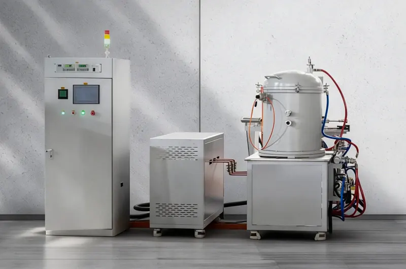
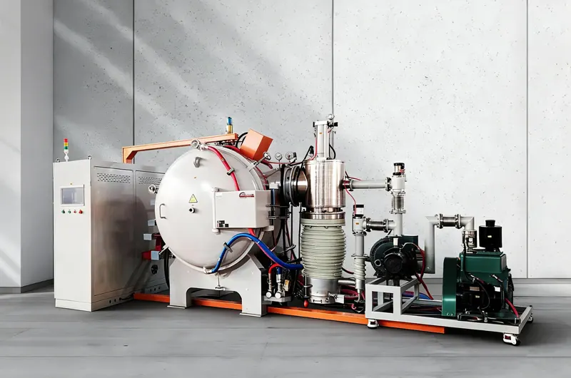
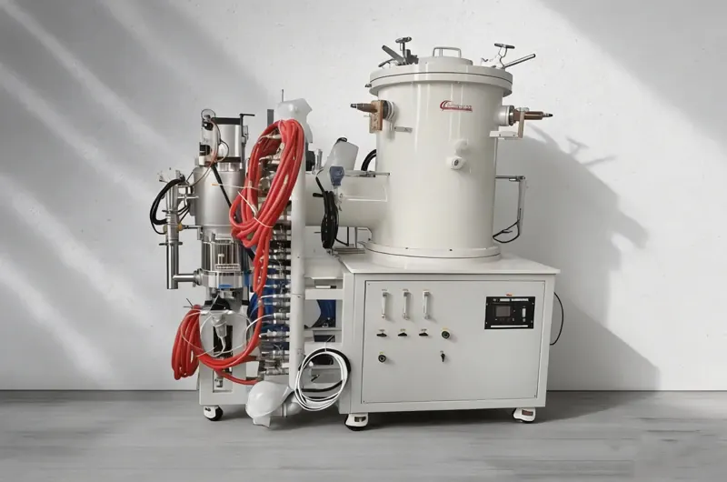
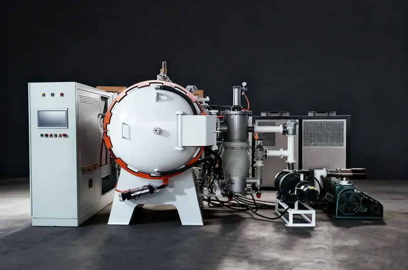
Selection Guide
How to Choose a Vacuum Sintering Furnace
Choosing a vacuum sintering furnace comes down to five variables: the material being
sintered, the temperature ceiling it needs, the batch size, the required vacuum or pressure level, and
how quickly the load has to cool. Work through them in that order and the correct furnace type
identifies itself.
Match the hot zone to the material first
The hot zone is the only part of a vacuum sintering furnace the load ever sees, so it decides what the furnace
can and cannot process. Graphite hot zones — graphite felt insulation with graphite or carbon-rod elements —
are the industry workhorse for cemented carbide, powder metallurgy parts and most structural ceramics. All-metal
hot zones built from molybdenum or tungsten strip and shielding are the choice when the material must never
contact carbon: medical implants, aerospace titanium, and carbon-sensitive advanced ceramics. Ceramic fiber
linings are lighter and cheaper, heat up faster, and suit laboratory and light-duty work where deep vacuum
matters less than cycle speed.
Set the temperature ceiling before anything else
Size the furnace around the working temperature your process actually holds — not the peak a datasheet can
briefly touch. A graphite hot zone runs continuously at 1800–2200°C and can reach a 2400°C peak. All-metal
molybdenum strip hot zones are usually limited to about 1600°C, because metal shielding evaporates and distorts
above that. Tungsten wire elements push the ceiling to roughly 2400°C continuous and 2800°C peak for refractory
metals. Graphitization furnaces are rated to 2900–3000°C, but under vacuum the practical limit is about 2200°C;
above that the process needs argon or nitrogen at slight positive pressure.
Size the hot zone to the batch, then add margin
Work from usable hot zone dimensions (width × height × depth) rather than chamber diameter, and include the
weight of fixtures, boats and setters in the load figure — not just the parts. A common mistake is buying on
peak load weight and discovering the working load is far smaller once a full fixture stack is inside. Leave
roughly 15–20% headroom so the furnace is not run flat out on every cycle.
Decide between vacuum, partial pressure and pressure
Deep vacuum in the 10⁻³–10⁻⁵ Pa range removes oxygen and drives off volatiles, which is what most sintering
cycles need. Partial-pressure operation with argon or nitrogen holds a controlled atmosphere while a binder or
lubricant burns off. Where residual porosity must be eliminated — cemented carbide, silicon nitride ceramic
balls, cutting tools — a Sinter-HIP cycle adds argon at 1, 6 or 10 MPa after sintering and can lift transverse
rupture strength by up to 50%.
Plan the cooling cycle before you commit
Cooling usually determines throughput more than heating does. Convection-assisted cooling under gas circulation
brings a 1450°C load down to handling temperature in well under an hour, against several hours for natural
radiation cooling in vacuum. If the furnace runs multiple cycles a day, specify the cooling system with the
same care as the hot zone.
| Application / Material |
Recommended Furnace Type |
Decisive Parameter |
| Cemented carbide (standard grades) |
Vacuum Graphite Sintering Furnace |
Graphite hot zone, 1800–2200°C continuous |
| Cemented carbide (low-cobalt, fine grain), cutting tools |
Vacuum Sinter-HIP Furnace |
Argon pressure 1 / 6 / 10 MPa, ±7°C uniformity |
| MIM stainless steel and titanium |
Vacuum Debinding and Sintering Furnace |
Integrated binder removal, ≥98% wax collection |
| Medical implants, aerospace titanium, carbon-sensitive ceramics |
Molybdenum Strip Chamber Vacuum Sintering Furnace |
All-metal hot zone, zero carbon contact, 10⁻⁴–10⁻⁵ Pa |
| Small parts, laboratory samples, rapid thermal cycling |
Vacuum Graphite Carbon Tube Furnace |
Tube geometry, 1600–2400°C, fast ramp |
| Tungsten, molybdenum, tantalum, large refractory parts |
Vacuum Tungsten Wire Sintering Furnace |
Tungsten wire elements, up to 2800°C, bottom loading |
| Transparent ceramics, sputtering targets, B₄C armour, metal matrix composites |
Vacuum Hot Press Sintering Furnace |
Single-axis pressure 10–50 MPa, 2000–2300°C |
| Lithium battery anode material, graphite film, carbon fiber |
Vacuum Graphitization Furnace |
2900–3000°C; vacuum limited to 2200°C |
| University and R&D pilot batches |
Ceramic Fiber Chamber Vacuum Sintering Furnace |
Low thermal mass, fast heat-up, 1200 / 1700°C |
Hot Zone Options
Hot Zone Materials Compared
Vacuum sintering furnaces are built around three hot zone families. Each one trades
temperature range, achievable vacuum and cleanliness against the others, and that trade-off — not the
outer chamber — is what separates one furnace type from another.
| |
Graphite Hot Zone |
All-Metal Hot Zone (Mo / W) |
Ceramic Fiber Lining |
| Working temperature |
1800–2200°C |
1300–1600°C |
1200–1700°C |
| Ultimate vacuum |
10⁻²–10⁻³ Pa |
10⁻⁴–10⁻⁵ Pa |
10⁻²–10⁻⁴ Pa |
| Carbon contact |
Yes — carbon source present |
None |
None |
| Best suited to |
Cemented carbide, PM parts, structural ceramics, magnetic materials |
Medical and aerospace parts, titanium, carbon-sensitive ceramics |
Laboratory samples, pilot production, light loads |
| Main limitation |
Carbon pick-up on sensitive alloys |
Lower temperature ceiling; shielding distorts at high temperature |
Absorbs moisture under vacuum; not for continuous heavy production |
Process Data
Typical Materials and Sintering Parameters
Sintering setpoints vary with powder grade, particle size and furnace load, so the
figures below are industry-typical starting points rather than fixed recipes. Final cycles are
developed on the customer's own material during commissioning.
| Material |
Typical Sintering Temperature |
Atmosphere |
| Cemented carbide (WC-Co) |
1380–1480°C |
Vacuum, then Ar pressure for Sinter-HIP |
| MIM stainless steel (316L, 17-4PH) |
1250–1380°C |
Vacuum with N₂ or Ar partial pressure |
| Alumina and zirconia ceramics |
1400–1700°C |
Vacuum or flowing Ar |
| Silicon nitride and silicon carbide |
1800–2200°C |
N₂ or Ar, often with pressure assist |
| Tungsten, molybdenum, tantalum |
2000–2600°C |
High vacuum |
| NdFeB and soft magnetic materials |
1050–1150°C |
Vacuum, Ar or N₂ |
| Graphite and carbon products |
2400–3000°C |
Vacuum up to 2200°C, then Ar or N₂ |
Customization
Standard and Custom Configurations
Every vacuum sintering furnace on this page is built to order around the load it has
to process. The list below covers the options most often specified; anything outside it can be
quoted once we know the material, the batch and the cycle.
- Hot zone size and shape — rectangular boxes, cylindrical zones, or tube geometry, sized to the fixture rather than to a catalogue number.
- Heating elements — graphite rod, graphite tube, molybdenum strip, molybdenum or tungsten wire mesh, matched to the temperature and cleanliness requirement.
- Control zones — two to six independently controlled zones with PID cascade control, typically holding ±3 to ±7°C across the working volume.
- Vacuum system — single-stage pump sets for 10⁻² Pa, or Roots and diffusion combinations for 10⁻⁴–10⁻⁵ Pa.
- Gas system — argon, nitrogen and hydrogen lines with mass-flow control, partial-pressure regulation, and pressure-assisted sintering up to 10 MPa.
- Cooling — forced gas circulation, external heat exchangers, and water-cooled jackets for short cycle times.
- Instrumentation — thermocouple and optical pyrometry, over-temperature interlocks, and process data logging with exportable cycle reports.
- Automation — recipe storage, automatic pump-down and backfill sequences, and remote diagnostics for service support.
Brother Furnace has built vacuum sintering furnaces since 2008 and ships to more than 80 countries, covering
laboratory units through to full production systems. Share your material, part size and cycle target and we
will recommend the furnace type, hot zone and configuration that fit — and quote it.